More with less
The More Electric Aircraft philosophy is increasingly being talked up as a potential weight-saver for future programmes.


Developed in the 1990s by the RTCA SC-180 committee, DO-254, a.k.a. “Design Assurance Guidance for Airborne Electronic Hardware”, was published in year 2000. In 2005, the FAA Advisory Circular (AC 20-152) recognised DO-254 as a means of compliance to the federal aviation regulations when complex custom micro-coded components are used in airborne systems. Field Programmable Gate Arrays (FPGAs) fall in the category of ‘custom micro-coded components’ and are increasingly being used in avionics roles. The designs (functionality) residing within the FPGAs must therefore comply with DO-254. However, DO-254’s style is very much objectives-based in that it spends a great deal of time explaining what should be done rather than explaining how to meet the objectives.
During the development of an FPGA, EDA tools are used for simulation, synthesis, place and route and static timing analysis, for example, so all have a role to play in DO-254 compliance. However, the FAA also recognises that other forms of EDA tool, most notably those that push harder into the verification space and/or provide traceability, can provide further design assurance for components with high impacts of failure. Specifically, the FAA has defined five hardware Design Assurance Levels (DALs), where DAL A denotes a ‘catastrophic consequence of failure’ and DAL B denotes a ‘hazardous/severe consequence’.
The linting process
Because DO-254 is effectively a ‘best practice’ document it should come as no surprise that adherence to coding standards is seen as a crucial aspect of design assurance for FPGA-based safety-critical applications; and the use of Hardware Description Language (HDL) coding standards is recommended by the FAA in Order 8110.105-2.a.
Verifying your adherence to best-practice coding standards is of course what linting tools have historically been used for. With its roots in the software industry, linting is a form of automatic Design Rule Checking (DRC) that can greatly assist hardware engineers developing FPGAs (and ASICs) as it has the potential to sanitise the HDL code before embarking on simulation and synthesis.
Linting is typically performed on the synthesisable Register Transfer Level (RTL) subset of the HDL, be it VHDL or Verilog, though it can also be applied at the gate level too.
Because simulation and synthesis can take a long time, particularly for high gate-count devices, it makes sense to go into both exercises with the cleanest code possible, thus minimising the risk of having to trace problems back to HDL. Linting performs a static analysis of the code, checking it against design rules. It also helps identify problems such as unreadable states within the finite state machine - i.e. dead code - thus enabling a reduction in the size or complexity of the simulation test vectors. In optimising the code, synthesis time will be reduced too.
Most linting tools come with pre-installed generic rules that check for potential RTL and post-synthesis simulation mismatches, design coding for optimal synthesis, avoiding problems on further design stages, and safe coding for portability and reuse. With a specific focus on safety-critical, in 2009, Aldec developed a DO-254 plug-in for its linting tool, ALINT (now superseded by ALINT-PRO), which includes checks for style, readability, simulation, clock/reset management, design re-use, coding for safe synthesis and implementation, clock domain crossings and design for test.
As rule checkers, linting tools will flag violations. Correcting the design and/or coding style will clear the violations in a subsequent run. Alternatively, the user can mark violations as ‘irrelevant’, provided justifications (i.e. comments) are made, and it worth noting that some linting tools can also output information essential for audits and reporting and review purposes.
In-hardware
Another aspect of DO-254 is that it requires that safety-critical designs be verified on ‘real hardware’, i.e. simulations - no matter extensive - will not suffice. But therein lies a problem. If you consider that an avionics LRU’s processor card might contain at least one FPGA (possibly with an embedded processor), responsible for time-critical functions, and that it will connect with a host of other board-mounted components; such as micros, DSPs, memory devices and possibly other FPGAs.
Requirements-based physical testing using the target circuit board is required for DAL A and B FPGAs. But this is not feasible in most cases. It is seldom possible to drive the target FPGA and capture its outputs - as defined in the requirements and test cases - because not all pins/pads will be accessible.
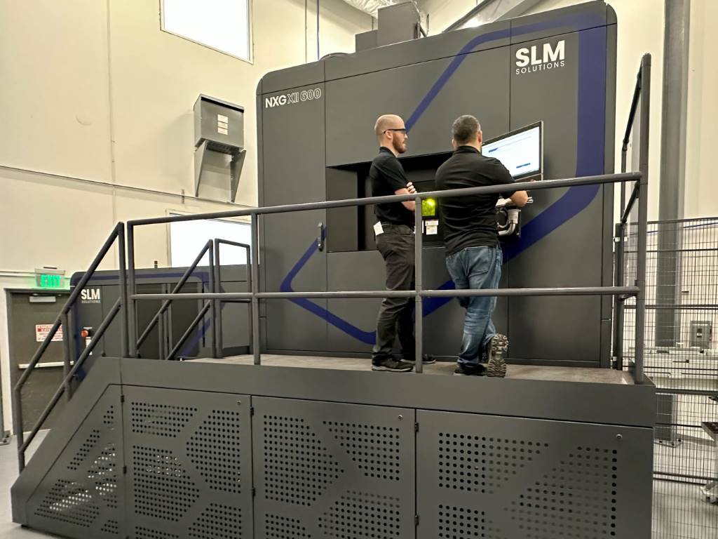
An alternative is to use a bit-accurate, in-hardware verification environment that enables requirements-based testing at the target FPGA, at speed, using the test vectors from the RTL simulation environment. Aldec’s solution is its DO-254 Compliance Test System (CTS – see Figure 1) which has a plug-in for storing the sequences of stimulators and events (outputs) produced during the RTL simulations.
This generates two sets of test vectors for all testbenches: Golden Vectors, which are the RTL simulation results and which will be used for comparison purposes; and Input Vectors, which will be used for at-speed, in-hardware verification. The Input Vectors are uploaded from a workstation to the motherboard. The CTS application software then controls the in-hardware verification process by feeding the Input Vectors to the FPGA pins at speed using real clocks. The results obtained are then sampled, again at-speed, and recorded in a waveform file. Compliance software then automatically compares the in-hardware verification results with the RTL simulation results (i.e. the Golden Vectors).
Traceability
Developing FPGAs for DO-254 compliance requires submitting extensive documentation to a Designated Engineering Representative; documentation that provides complete traceability throughout the development lifecycle of the equipment (for example a Line Replaceable Unit) including any complex custom micro-coded components used therein. Again, EDA tools can help.
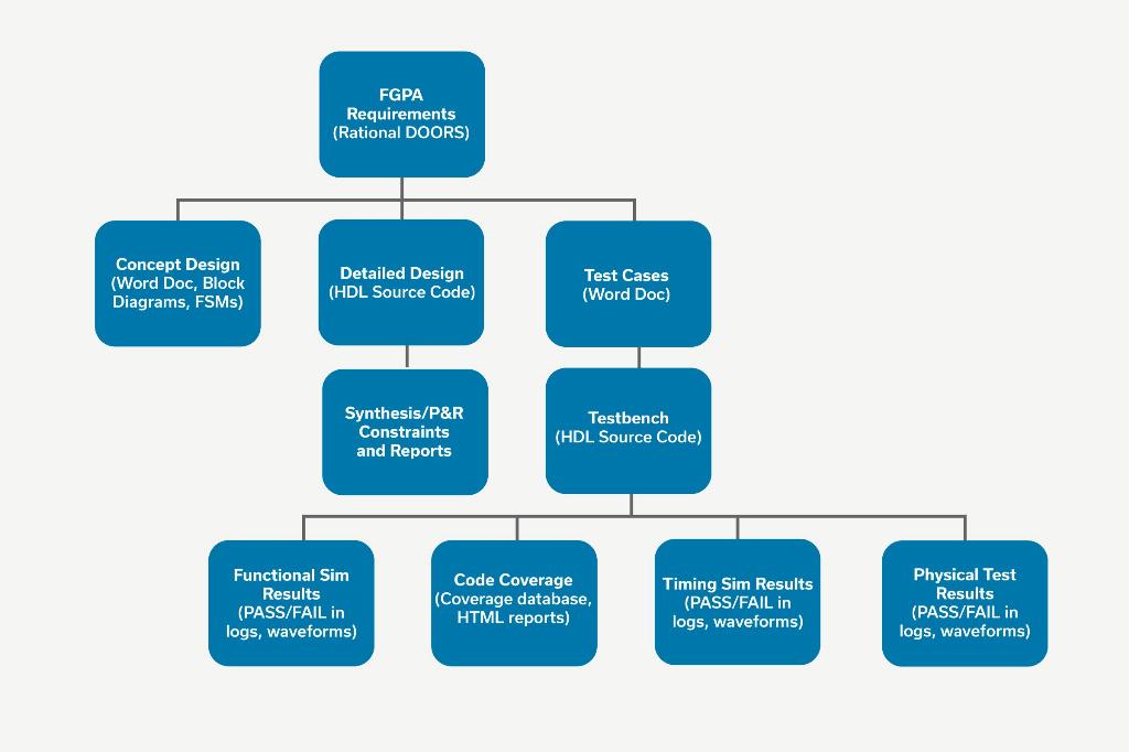
In Aldec’s case, its Spec-TRACER tool streamlines the requirements engineering process from capture through to tests management, and establishes and maintains traceability for all sources of input into the project (see Figure 2).
FPGA requirements are automatically traced down to the HDL design, testbench sources and test results, thus allowing designers to record how every requirement within the spec’ was implemented and verified. Moreover, gaps (i.e. parts of the spec’ not implemented and verified), as well as unused HDL functions, are easily exposed.
In addition, and as we are all aware, requirements can and do change throughout a typical project. To this end, Spec-TRACER is equipped with built-in reporting for Impact Analysis, and it can determine the magnitude of any and all changes before they are made.
In summary
Whilst naming a few products in passing - because 2017 marks the 10th anniversary of Aldec helping customers comply with DO-254 - the underlying message is that providing the levels of assurance demanded by the FAA for FPGA-based, safety-critical avionics functions requires fit-for-purpose EDA tools. One has to be able to prove that the design will and does function as intended. The proof can be provided by a mix of design automation and project management tools, used throughout the entire development lifecycle.