Ensuring zero internally threaded fastener defects
New high-speed sorting technologies, including vision based hole and thread detection, are making traditional methods obsolete


In this article for Aerospace Manufacturing Olympus discusses the benefits of its remote visual inspection and measurement systems for viewing the inside of aircraft engines.
The aerospace industry has come a long way since the first successful, sustained human flight on 17 December 1903. For more than a century aircraft structures have evolved from the early beginnings of wood and cloth to the present day, where those materials have been replaced by complex alloys and composites. Likewise, the power sources have changed from the dominance of the internal combustion engine to the introduction of highly efficient gas turbines.
One area which remains as important as ever, but which has evolved organically alongside the evolution of the modern aircraft, is the aspect of safety, and the significance of maintenance and testing in ensuring the continued safety of flight.
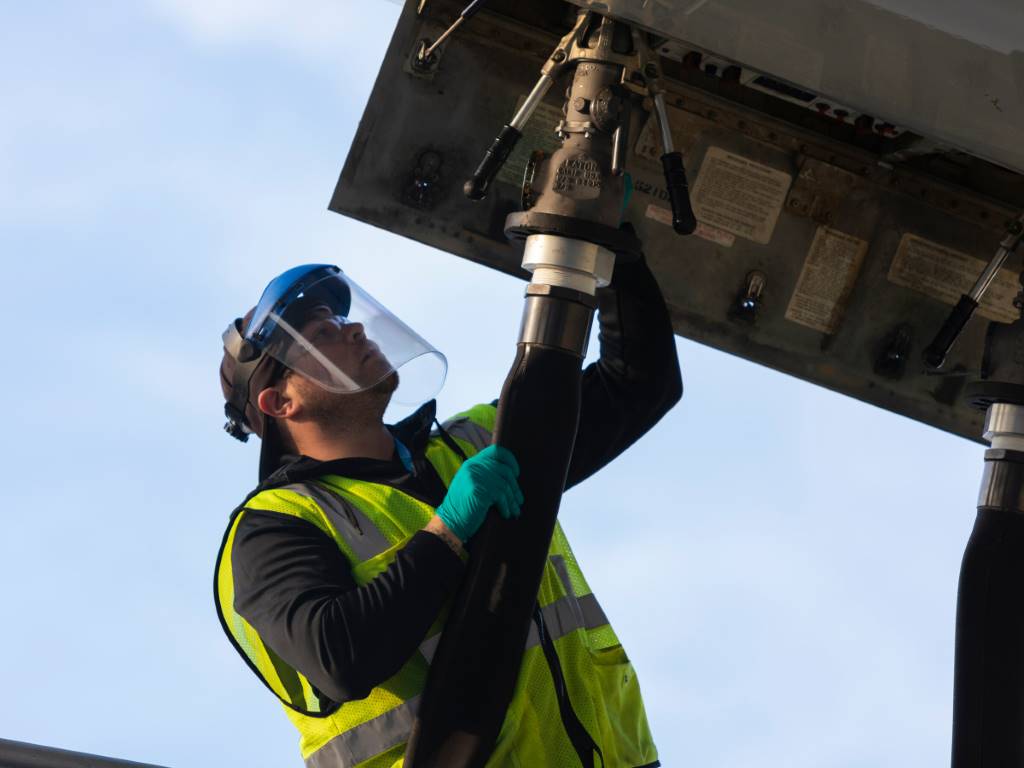
During this evolution, the requirement for testing of critical structural components of both commercial and military aircraft has increased significantly. Regular inspections of hundreds of critical areas on each aircraft, as well as careful attention to quality assurance in the manufacturing process, are essential to maintaining the aerospace industry’s outstanding safety record. Aircraft manufacturers and operators use a variety of non-destructive testing (NDT) methods and other inspection technologies in these examinations, with different methods being best suited for specific tasks in different areas, and these are recommended accordingly in the corresponding manufacturer’s test procedures and service bulletins.
Challenges and solutions
A gas turbine is subjected to extremely high temperatures at take-off, the RB211-524 used to power a 747-300 (Jumbo Jet) reaches temperatures in excess of 1,400°C at 430psi. At these temperatures there is the potential for parts of the engine, after the combustion section where ignition takes place, to melt instantly if it were not for the clever design of the components which make up this turbine section. Each component is covered in a special plasma based thermal barrier coating and hundreds of small holes are designed into the components – specifically nozzle guide vanes and turbine blades – allowing a cushion of comparatively cooler air to pass over the components thus protecting them from the intense heat.
Of course, the potential for these cooling holes to become blocked can lead to portions of these turbine blades to become damaged, and the aerospace industry has a number of guidelines in place to confirm how large a defect can be before it becomes averse to safety. As such, during routine inspection, these defects (if any) are monitored using remote visual inspection (RVI) techniques and measured to determine if the aircraft can be deemed airworthy again.
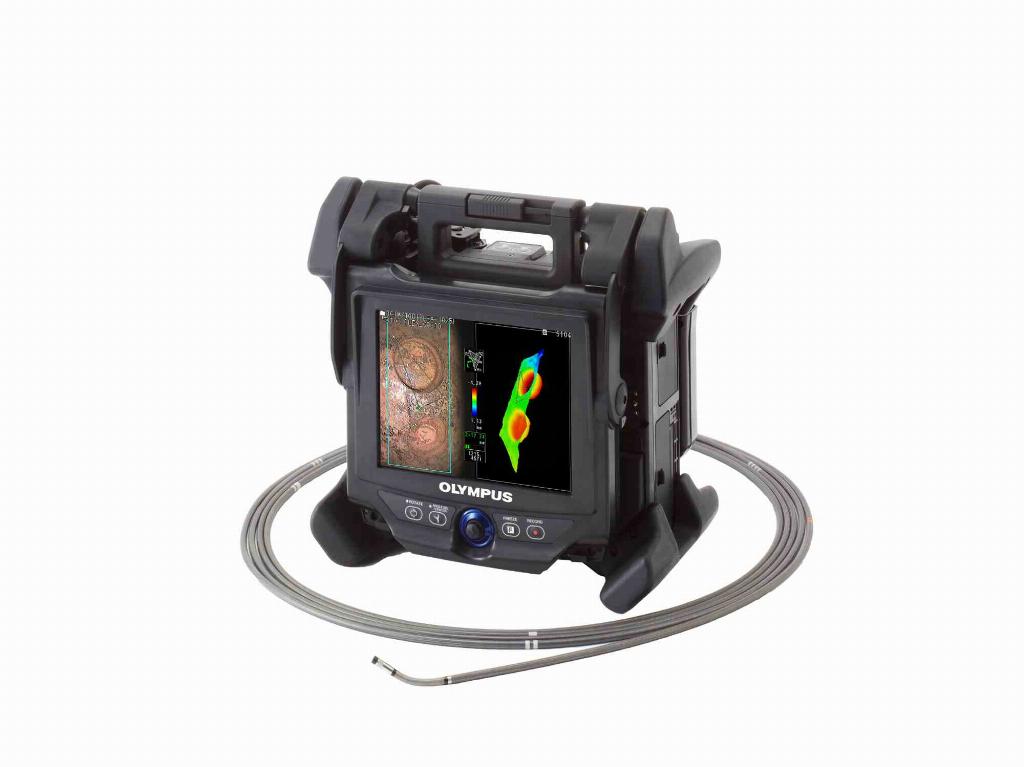
Gas turbines present a challenging environment in which to work with a videoscope or video borescope, with some areas being highly reflective, such as turbine blades and burner assemblies; and some areas extremely dark, such as the combustion chamber, nozzle guide vanes and areas of the turbine. Capturing a bright, sharp and clear image in these areas is equally difficult, and certain advances in RVI technology have helped to improve workflow, providing inspectors and operators with an easier platform with which to obtain the best possible images.
Some of the key benefits of Olympus’ inspection system are: bright, high-resolution images that faithfully and clearly reproduce very small defects within a gas turbine for accurate analysis; insertion tubes with well-tuned stiffness and flexibility, and often TaperedFlex technology which facilitates insert-ability for smooth all-round inspections of the shroud and combustion chamber. TaperedFlex technology is also exceptionally resilient and can withstand repeated use against sharp blades and other metal surfaces. Other Olympus benefits include TrueFeel articulation that provides exceptional control and precision to improve work efficiency and Advanced 3D measurement technology that is suitable for defect measurement on engine blades located in narrow and hard-to-approach areas.
With this new approach to measurement image acquisition and manipulation, users are now better placed than ever before in making not only accurate, but repeatable measurements with increased confidence.
Choosing the right measurement point is now even easier with 3D modelling enabling an inspector to see the details of what they are inspecting from multiple angles, making it easier to specify the exact location of their measurement points in 3D space, in an area four times larger than conventional videoscopes.
Single-handed inspection
Due to the hundreds of turbine and compressor blades found in an aircraft engine inspection of the parts can become a laborious task when rotating the engine shaft.

Furthermore, because operators need to inspect hundreds of blades, which are located at several turbine/compressor stages and mounted on the shaft during the aircraft engine inspection, a collaborative approach is required where one operator manually rotates the shaft while another inspects the blade condition. This work not only requires an additional operator for the shaft rotation, but also tends to cause insufficient inspection of the components.
With the Olympus’ engine specific OTT (Engine Turning Tools) the system can automatically rotate the shaft with high-pressure compressor/turbine blades at a preferred speed, enabling an inspector to accurately and thoroughly conduct both the shaft rotating and blade inspection operations without the need for a second person.
Organising the image
Throughout the inspection, recording a large number of blade images is often the case for inspection analysis and report generation, but within this environment, images are very similar to each other and it is sometimes impossible to identify blade types by reviewing them. Thus, many operators experience difficulty and frustration when attempting to find and sort intended images from a large volume of very similar photos that have been taken.
InHelp, Olympus’ inspection assist system for industrial endoscopes presents itself as the perfect tool for condition monitoring and trending, image and file management and reporting.
By conducting an inspection as guided by the InHelp functions, operators can classify inspection images into folders and also add judgment results and fixed comments to the images. After the inspection a report containing more than 50 images can be generated within minutes by utilising the InHelp Viewer software and customised report format.
Olympus provides effective systems to increase work efficiency of aircraft engine inspections. The OTT Engine Turning Tools allow an inspector to conduct inspections of high-pressure compressor/turbine blades single-handedly. The InHelp Inspection Assist Software streamlines all aspects of the inspections and significantly reduces the time for post-inspection work.