Mazak reports strong machine tool sales in 2021
The economic rebound from COVID lockdowns enabled Yamazaki Mazak to record a strong year for machine sales in 2021, including a record month in late autumn.


DMG Mori manufactures a wide variety of conventional chip-cutting and ultrasonic CNC machining centres that serve the aerospace industry. Inherent in this industry are several factors that require great care and planning in the machining process. Typical components produced include those made from lightweight, but hard materials, such as titanium and related alloys, as well as aluminium workpieces where substantial volumes of material removal occur, such as fan blades and blisks. Due to long cycle times and high raw material costs, the machining of such components presents a challenge to part production departments and job shops alike.
On two recent applications, DMG Mori turned to business partner, Siemens for assistance. Offering a total package of CAD/CAM/CNC hardware, software and engineering services, Siemens was able to help DMG Mori substantially improve every aspect of part production, including reduction of design-to-part protocols, machining time, tool life, surface finish, dimensional accuracies and overall production efficiencies.
Streamlined simulation
In the first instance, a reverse thrust component for an aero engine was to be made from Ti Gal-4-V, owing to its elastic stiffness. Starting from the CAD file, the Siemens PLM team ran the program through its NX CAM with a VoluMill add-on feature that calculates for maximum material removal rates. The User Defined Events (UDEs) feature inside the NX program allows simple check boxes for triggering post-processor references for coolant pressure, amplitude, ultrasonic generator settings and more. This avoids manual programming and, as a result, reduced the program transition time from as long as two days to approximately 30 minutes.
Once the program was ready for the control, the features of the Sinumerik 840D sl CNC allowed a more streamlined simulation of the actual cutting path. The 3D quick set compressor feature provides a parametric itemised data file for all path motions, thereby eliminating collisions and ensuring the optimum tool path, in conjunction with the NC kernel and PLC on the machine tool.

As Siemens technical applications centre manager, Randy Pearson observes: “This feature is a huge time saver for our customer, as the test ball and probe in the spindle mechanism can be run at any point in the cycle, testing the actual machine kinematics at any time. The procedure can also be automated to run on the table at prescribed time intervals.”
The high-speed machining feature is highlighted by Cycle 800, a static plane transformation that allows a 5-axis machine to define a rotated working plane in space. It’s known in the industry as 3+2 programming. The cycle converts the actual workpiece zero and tool offsets to refer to the rotated surface. Of note here, the cycle accommodates particular machine kinematics and positions the physical axes normal to the working plane. This is referenced as TRAORI or transformation orientation.
Meanwhile, the Sinumerik CNC Operate user interface on the machine allows the operator to perform a variety of integrated tool management and information management functions, all transportable on a USB or network connection.
In the simulation, the loading and fixturing of the workpiece is performed virtually in NX CAM, which also calculates a consistent chip load, critical in these large material removal applications. The simulation further verifies the tool length at every cutting section and the program is finalised for the machine to begin. It’s literally like working with a ‘digital twin’ of the machine.
During production, this process yielded a 2.25x improvement in tool life on this very hard material, according to DMG national product manager, Luke Ivaska.
“With the combination of NX CAM, plus the Sinumerik 840D sl on the machine and all it could do, we had some initial challenges, as most software programs are purpose-built CAM packages that allow quick and easy use by anyone. They have significant limitations; however, as the software drives the tool path and the operator has very little control. With NX CAM and Sinumerik, we’ve a lot more input on the creation of the tool path. I’ve yet to find a problem I couldn’t solve with NX.”
The finished part is run in 4-½ hours with a surface finish improvement from 62.5 Ra to 35 Ra, due to the ultrasonic actor.
Getting out of a tight spot
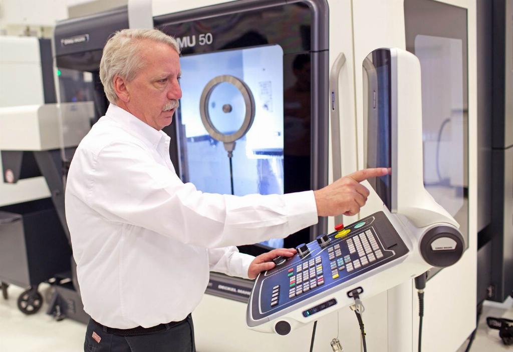
In the second example, an entry-level DMU 50 5-axis machining centre is utilised to cut a 7” diameter x 2” high block of 6061 aluminium into an aerospace impeller fan, with more than 90% material removal achieved. The same NX CAM software began this process chain, with the initial benefit of considerable time-savings in the 5-axis setup and comprehensive G-code simulation and verification in a single system. Because of the bladed structure of this impeller fan component, only a 0.5° clearance between the part and the toolholder was allowable during machining. Simulation with NX CAM is key to getting in a tight spot without collision of tool and part. DMG Mori looked to long-time tooling partner, Haimer, and its slim line holder was deemed a viable solution for this application. Meanwhile, the interpolated tool axis and section views were run on NX CAM to verify the operation of the tool in this very tight workspace.
In the Sinumerik 840D sl, the same 3D quick set compressor feature ensured the proper tool path, while the high-speed machining setup and Cycle 800 were again utilised for this project. Sinumerik Operate, the CNC’s graphical user interface, affords the end user’s operators and manufacturing engineering personnel full access to a variety of conditions in production, including all roughing and finishing data in plain text, plus all 5-axis transformation orientation data logged for restart after any interruption and manual restart.
The variable streamline operation of the machine tool combines with an interpolated vector to produce a smoother finish in the machining of the blade surfaces in a single tool path. The machine seamlessly transitions from square-to-round machining and then the extreme angle paths needed to accurately machine the blade internals. The single blade fin portion of the program was automatically captured, so a step-and-repeat program can be built-up. The simulation of each blade fin cutting path was done on both the NX CAM and the CNC programs.
This vectored program is transportable to any machine with comparable results, according to Pearson and Siemens PLM director of business development, Matthias Leinberger, who comments: “Precisely because the machine kinematics are knowable, this program, once created, can be transferred onto multiple machines within the same facility or run by shops around the world, all tied together by the control, so there is total continuity between the operations, the data capture protocol and feedback received for production analysis.”