Seco’s ITI gives real world solutions to aerospace manufacturers
With the value of collaboration in mind, Seco and its technical partners hosted Inspiration Through Innovation (ITI) from 23-24 November for aerospace manufacturers.


The high volume of orders in the aviation industry places great pressure on the capacity of engine manufacturers and their suppliers. Therefore, a reduction in component machining times would be highly beneficial. For heat-resistant super alloys, the cutting speed of carbide milling cutters is approx. 50m/min. Ceramic milling cutters offer a different approach, with cutting speeds of up to 1,000m/min.
The Walter product range includes two series of ceramic milling cutters: The MC275 with universal geometry is suitable for most applications; the MC075 is designed as a high-feed milling cutter. Both product ranges (see image 1) are available with cutting diameters of 8 to 25mm. Tools with diameters of 8 to 12mm are available as integral milling cutters, while tools with diameters of 12 to 25mm are available as ConeFit milling cutters. In both cases, only the head of the tool is made from ceramic. This head is brazed onto either a carbide shank or a carbide ConeFit base body. In principle, the entire milling cutter could be manufactured from ceramic, but a carbide shank increases the strength and damping of the tool. This enables increased projection lengths and higher material removal rates in comparison to solid ceramic tools.

Dynamic with ceramic
The range of applications of ceramic cutting tool materials includes nickel-based, cobalt-based and iron-based heat-resistant alloys in the ISO S group. Typical alloys are for example Inconel 718, René 80, Nimonic 80A, Haynes 556, Mar-M-247 and Stellite 31. These heat-resistant super alloys (HRSAs) are the preferred choice for use in the hot section of aircraft engines.
The ceramic cutting tool material is tailored for use in milling applications. SiAlON ceramics are more resistant to temperature fluctuations than whisker-reinforced ceramics. This makes them the ideal choice for milling operations. The interrupted cut causes the temperature on the cutting edge to vary, and the use of coolant media can further increase the temperature difference, resulting in a thermal shock effect. For this reason, Walter recommends dry machining when machining high-temperature super alloys with ceramic milling cutters. An additional benefit for users is the environmental and economic advantage they gain from avoiding use of cooling lubricants.
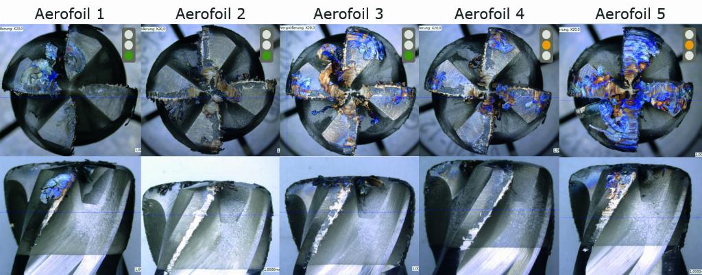
The primary causes of wear when milling nickel-based alloys with ceramic tools are chemical wear caused by the temperature and built-up edges. While chemical wear or diffusion wear continuously weakens the cutting tool material, wear caused by build-up on the cutting edge is unpredictable and occurs in sudden increments. As a result of the high machining temperature (see image 2) and the high toughness of high-temperature super alloys even at high temperatures (for example Inconel 718; Rm = 880N/mm² at 750°C), a large build-up of chips can form on the tool. These can fuse to the surface of the cutting material and cause parts of the ceramic to chip off when removed. The built-up edge on the tool can be clearly seen in image 3. Even though the high temperature resulting from machining of HRSAs has a negative impact on tool life, it is necessary. This is the only way to reduce the hardness of the material and to machine it efficiently.

The cutting data is predetermined by the cutting tool material and the material to be machined. A brittle yet heat-resistant cutting tool material can be used at high temperatures, but the low impact strength demands low feed rates per tooth of 0.02 to 0.05mm and small tool engagement of ap = 5% of Dc for full slotting operations and ae = 5% of Dc for contour milling with maximum cutting-edge length. The exception to this is the MC075 with high-feed geometry where fz = 0.15mm for ap ≤ apf. The cutting speed for both product ranges are between 400 and 1,000m/min.
The results for milling cutters with carbide cutting edges and milling cutters with ceramic cutting edges could not be more different. The wear photos in image 3 show why ceramic milling cutters are only used for roughing. Signs of wear such as chipping on the cutting edge and wear mark widths of over 0.5mm, which for carbide milling cutters would indicate end of tool life, are no reason to stop using a ceramic cutting tool. The differences between the two cutting tool material types are also made clear by comparing the cutting parameters.
A comparison between end milling cutters with a diameter of 10mm used for full slotting of Inconel 718 is used as an example (see table in image 4). The significantly higher feed rate provided by ceramic is an unbeatable advantage, despite the greater depth of cut provided by carbide. In this case, the metal removal rate using a ceramic cutting edge is 56% higher. In addition, the total volume of metal removed using the ceramic milling cutter is 180% higher than the carbide milling cutter. Metal removal rates and the total volume of metal removed per tool life are the parameters where ceramic offers clear advantages over carbide. The shorter machining time enables larger batch sizes to be machined using the same machinery; the option for users to configure their existing machinery enables them to get by with fewer machining centres. The high total machining volume reduces tool costs.
A classic example of a component made from a nickel-based alloy is a blisk for aircraft engines. This rotating integral component is a disc with a large number of blades. The spaces between the blades can be milled out using carbide milling cutters via a roughing process. The machining time for this is approximately 30 minutes. The MC075 ceramic milling cutter with high-feed geometry can carve out the same spaces in 10 minutes. For this application, it achieves feed rates of 9,500mm/min in a heat-resistant nickel-based alloy with a hardness of 44 HRC and a tensile strength of 1400N/mm². Feed rate values such as these are generally expected for machining aluminium, rather than nickel-based alloys.
While ceramic tools present excellent machining opportunities, it is nevertheless worth considering whether the high machining temperatures that ceramic milling cutters reach could result in damage to the material. As ceramic tools are only used for roughing operations, the only thing that needs to be ensured is that the depth of the damage to the material is less than the offset for finishing. In collaboration with Fraunhofer IPT in Aachen, Germany, the depth and extent of hardening was measured – for ceramic milling cutters with different levels of wear, in a full slotting operation in Inconel 718. The hardness measurement was carried out after the ceramic tools had been used to mill 13 or 14 slots with medium wear, or 23 slots with very high wear, in each case.
The measuring points on the slot were selected in order to determine and evaluate the maximum thermal load. The basic hardness of the material is 446 HV. The result: A hardening of up to 640 HV was detected within a depth of 100µm. No hardening could be detected at depths greater than 200µm – regardless of the wear of the tool or the direction of measurement. As the generally applicable roughing offset is between three- and five-tenths of a millimetre, it is therefore not expected that roughing using ceramic tools will result in any damage remaining after the finishing process.