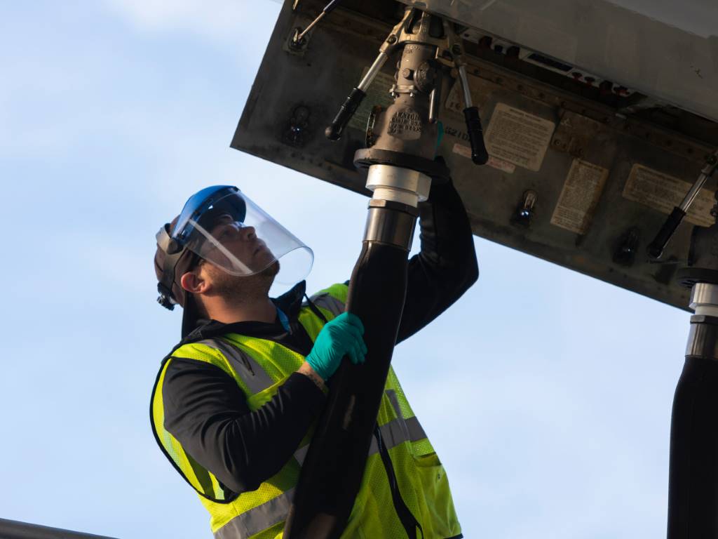
Ensuring zero internally threaded fastener defects
New high-speed sorting technologies, including vision based hole and thread detection, are making traditional methods obsolete


If you are looking to carry out reliable and efficient aircraft engine inspection, Evident Scientific provides its videoscope guide to improve the accuracy of blade tip clearance inspection. Aerospace Manufacturing reports.
During an aircraft engine inspection, measurement or quantitative analysis using a videoscope is performed to accurately determine the degree of defects. Reliable assessment using remote visual inspection enables aircraft maintenance technicians to carry out the appropriate repairs or part replacement.
Videoscopes configured for stereo measurement are widely used for aircraft engine inspections because good measurement results can be obtained when measuring objects in tight spaces, such as in high-pressure turbine (HPT) stages, commonly known as the hot section. In recent years, videoscopes with 3D modelling functions have further improved the reliability of measurements in HPTs by displaying the 3D surface shape of turbines during inspections.
A verification in the HPT that can benefit from a videoscope with stereo measurement and 3D modelling is blade tip clearance inspection. Part of the quality check of in-service turbine engines, a blade tip clearance inspection involves measuring the gaps between the engine shroud and the blade tips. A smaller gap clearance than the defined tolerance may result in damage to both the shroud and blades, while a larger gap reduces combustion efficiency and engine performance.
For high accuracy during a blade tip clearance inspection, the videoscope image acquisition and measurements need to be executed in a proper manner. To assist your blade clearance inspection, here are a few techniques for capturing images - some tips for taking accurate measurements will follow.
Tips for capturing images during blade clearance inspections:
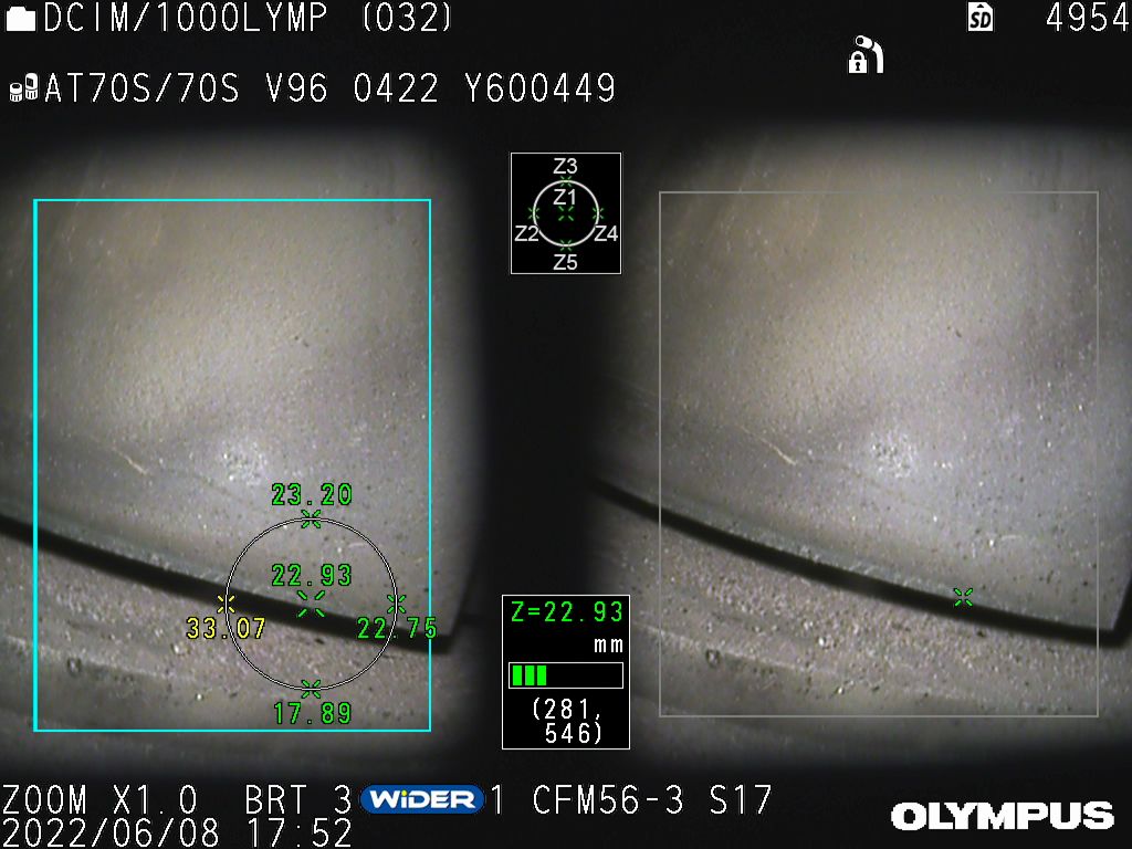
This angle adjustment technique helps to counteract the problem shown in Figure 1a on the left. When the root side of the blade is in the back and the edge side of the blade is in the front, the difference increases between the left and right shroud images. Consequently, the likelihood for incorrect measurement results is also increased.
Tips for taking accurate measurements:

Videoscopes offering stereo measurement and 3D modelling are advantageous for taking measurements - whether for quality checks or assessing defects - in aircraft engines. They offer easy operation and high measurement accuracy. For blade tip clearance inspection, which targets uniquely shaped objects, stereo measurement improves the image acquisition reliability, and 3D modelling helps ease the execution and improves the measurement accuracy.
For reliable and efficient aircraft engine inspections, including blade tip clearance inspections, it is important to choose a videoscope capable of stereo measurement with optimised design features, such as a scope tip with a short rigid portion to ease insertion, and support functions that facilitate measurements, such as 3D modelling with zoom and a real-time object distance indicator.