Axes of production power!
Aerospace subcontractor, TGM expands its 5-axis machining capabilities with the latest addition of a Hurco SR series CNC mill.


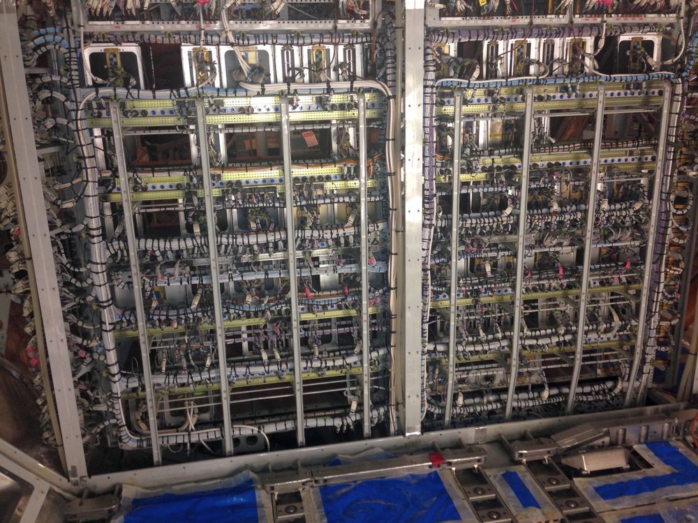
Electrical design projects in the aerospace industry are typically large, complex and involve numerous stakeholders. For instance, the interconnection of an aircraft’s avionics systems, engines, electrical loads, sensors, user interfaces and lighting etc. requires hundreds if not thousands of wires. In the case of the Boeing 787, it has between 60 and 70 miles of wiring, and the Airbus A380 has an estimated 300 miles.
The creation of wiring (harnesses) involves many stakeholders including software, electronic, electrical and mechanical engineers. Other stakeholders include personnel in purchasing and QA plus specialists in regulatory compliance. Also, in a bid to reduce overall costs and shorten the time to production, there are increasing levels of collaboration with and between external suppliers.
Accordingly, for projects to run smoothly, all stakeholders require access to the most appropriate data, i.e. that which pertains directly to their activities, and that the data be current.
Let’s therefore consider what’s involved in designing, manufacturing and then maintaining the wiring harnesses of an aircraft. The sheer length of some runs will make routing very challenging, and wires will seldom be able to take the shortest route from A to B. Also, there should be sufficient slack and flexibility to accommodate installation in the airframe and to allow access to serviceable items (i.e. components which can only be reached by moving wiring aside). And let’s not forget that aircraft tend to receive a few upgrades and modifications throughout their lives. No wiring harness should therefore ever be regarded as a fit-and-forget item.
Meeting the challenges
Designers and manufacturers live with the ever-present twin pressures of time (to installation, integration, commissioning and operation) and cost. Designs must be right first time, and there can be no surprises during assembly.
As for the routing of the cables, that responsibility lies mainly with mechanical engineers. Working in a 3D environment, they will place components and route the cable sets. Here, the level of interaction between the electrical and mechanical design engineering activities will have a direct impact on the success of the project.
Aiding in the design process is the good level of integration between electrical and mechanical computer aided design tools (ECAD and MCAD respectively). For instance, many tools allow electrical connectivity to be established in a 2D environment, i.e. a traditional schematic, and for the design to then be exported via a bridging interface into a 3D MCAD environment.
It is at this point the design can take on physical characteristics, such as wire and bundle diameters, inherited from data within the ECAD tool. Once routed, the harness can be analysed in a variety of ways. It can also be imported back into the ECAD tool to create drawings, as wire lengths are now known as are intended positions of ties and clips.
Most ECAD tools have a good level of intelligence too these days, with rules for checking that short circuits are never made during schematic capture and that devices have unique names. Most also allow for connection types to be categorised as digital, analogue or power, which can greatly aid routing.
Customisable rules help too, governing, for instance, the maximum number of wires that can connect to a given connector pin, as well as the wire gauge limits. Verification checks will typically include flagging any unconnected pins, wires not assigned pins/connections yet, unplugged connectors and incorrect option codes.
This last check is particularly useful if the aircraft is to be highly customisable, as tends to be the case for business and VIP jets. There may be a core (or reference) electrical architecture which needs to be modified depending on the options and variants selected by the customer. Not all options and variants might be viable though, so some ECAD tools employ Boolean logic based algorithms to ensure only viable permutations can be presented.
For manufacturing purposes, the more that can be automated the better. For instance, data from the electrical design domain can be used to drive a strip-cut-mark machine, of which the ‘mark’ aspect should be utilised to the full. By automatically adding tags/labels carrying connector and pin references towards the ends of wires you can remove any ambiguity during assembly.
For the fitting of aircraft components and cable sets, it will typically be necessary to follow a specific sequence. To assist, some manufacturing tools can show the assembly personnel the precise build sequence, stage-by-stage. For instance, the wire associated with a particular stage can be highlighted on a 3D drawing and accompanied by details of its connections at both ends. Accordingly, it becomes possible to perform the assembly tasks without recourse to schematics and/or the drawings used for the wiring harness form board.
All together now
The total data set for a wiring harness is likely to include a schematic, a wiring plan, a bill of materials, assembly notes, fuse ratings, switch settings and datasheets. In this respect, some ECAD tools now have an object-oriented systems architecture and are built on a central database.
This ensures continuous synchronisation between all engineering stages, and supports concurrent engineering within any given project. Also, if there are multiple projects, sound data management will be essential for version control and managing options and variants.
In summary, by making better use of the data within a project, companies will save money in both the short-term (because there is less risk of design and/or manufacturing mistakes being made), and in the long-term (because the aircraft will be easier to maintain and upgrade). In addition, the wealth of documentation needed for assembly and maintenance purposes can, and should, have its roots in the electrical, mechanical and software design domains.